TWW103 M1 (VMD-TWW103-M1) Transmitter

Description
| Manufacture | Others |
| Model | TWW103 M1 (VMD-TWW103-M1) |
| Ordering information | TWW103 M1 (VMD-TWW103-M1) |
| Catalog | Vibration Monitoring |
| Description | TWW103 M1 (VMD-TWW103-M1) Transmitter |
| Origin | United States (US) |
| HS Code | 85389091 |
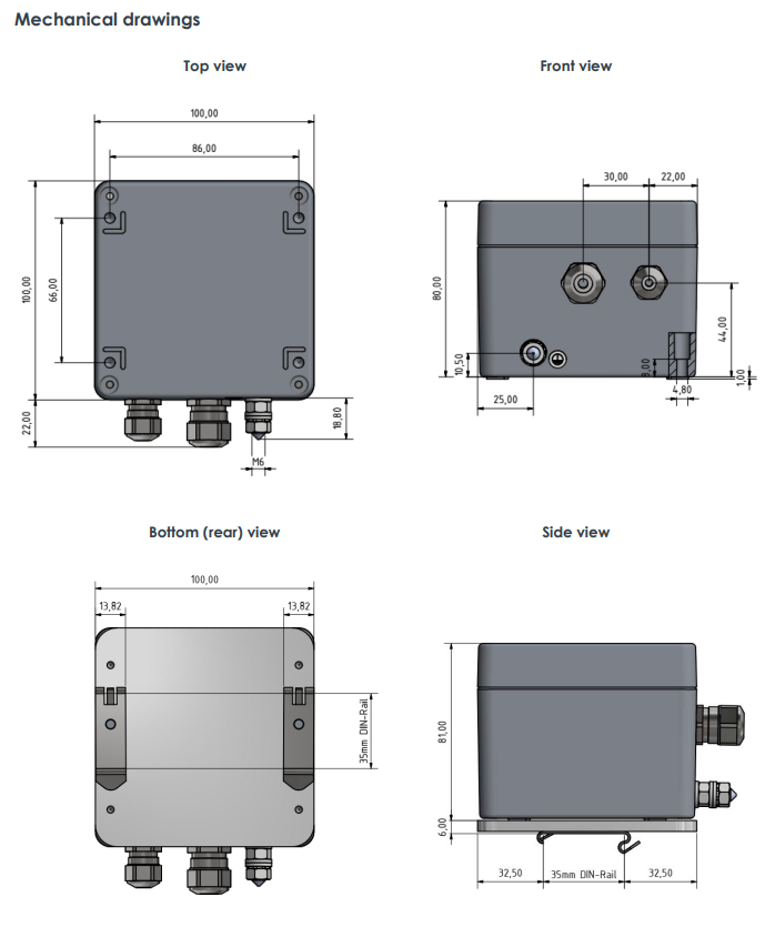
| Dimension | 16cm*16cm*12cm |
| Weight | 0.8kg |
Details
The TWW 103 M1 transmitter is a dedicated onechannel vibration and position measurement transmitter with a 4 to 20 mA current-loop output signal. A TWW 103 M1 transmitter is used, in combination with a WW 018 proximity sensor, to measure the relative position of a target object without touching the target (that is, the non contact measurement of displacement). Accordingly, such displacement measurement systems consist of a WW 018 proximity sensor and a TWW 103 M1 transmitter, and provide a measurement range (static) of 10 mm. The TWW 103 M1 is available in standard versions for use in standard (non-hazardous) areas and Ex versions for installation in hazardous areas (potentially explosive atmospheres).
General operation
Sensor compatibility : WW 0xx proximity sensor with a cable length of 5 m.
Notes: The system length must be specified when ordering.Sensors of the same type with the same cable length are interchangeable.
Measurement range : 10 mm max. with WW 018 proximity sensor.
Note: The measurement range depends on the sensor.
Linearity deviation : ≤2%.
Note: Measured with a reference WW 018-R proximity sensor.
Filter
• Low-pass filter (fu) : 0 Hz
• Low-pass filter (fo) : 5 Hz
• Roll-off (slope) characteristic : 20 dB/decade
Internal supervision : Internal supervision circuitry (transmitter) monitors for interruption or a short-circuit in the proximity sensor or in the cabling. Furthermore, it will also detect when the target object is clearly placed outside of the measurement range.
Fault indication : Zero current (0 mA) signal from the analog output and a red LED indicator (see LED indicators on page 3)
Analog outputs
• 4 to 20 mA : 4 to 20 mA current loop output, corresponding to the processed output measurement (relative position).
Notes: 500 Ω max. load. This signal is the main output from the transmitter intended to be used for machinery monitoring.
• 4 to 20 mA (25 Ω) : 4 to 20 mA current loop output, corresponding to the processed output measurement (relative position).
Notes: 25 Ω max. load. This signal is intended to be used for the positioning of the proximity sensor (during installation).
Notes: Both analog outputs are galvanically isolated. The analog output characteristic is inversely proportional to the input, with 0 to 10 mm corresponding to 20 to 4 mA.
Offset : Inaccuracy in the mechanical installation (positioning) of a WW 0xx proximity sensor can be corrected using the Z potentiometer. The range of compensation corresponds to ±0.5 mm approx.
Power supply Voltage : 24 VDC nominal (18 to 30 VDC).
Note: Galvanically separated.
Current : 100 mA max.