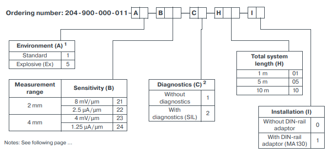
IQS900 204-900-000-011 A1-B23-C1-H05-I1 Signal Conditioner

Description
| Manufacture | Others |
| Model | CA901 |
| Ordering information | 144-901-000-282 |
| Catalog | Vibration Monitoring |
| Description | CA901 144-901-000-282 Piezoelectric Accelerometer |
| Origin | United States (US) |
| HS Code | 85389091 |
| Dimension | 16cm*16cm*12cm |
| Weight | 0.8kg |
Details
The IQS900 signal conditioner is a versatile and configurable device that performs all required signal processing and generates the output signal (current or voltage) for input to a machinery monitoring system such as a VM600Mk2/VM600 . In addition, the IQS900 supports optional diagnostic circuitry (that is, built-in self-test (BIST)) that automatically detects and remotely indicates problems with a measurement chain.
The IQS900 signal conditioner contains a highfrequency modulator/demodulator that supplies a driving signal to a TQ9xx sensor. This generates an electromagnetic field in the tip of the sensor, which generates eddy-currents in the metallic target. When the target moves, the eddy-currents change, which causes a change in the electrical characteristics of the TQ9xx that the signal conditioner converts into a signal that is proportional to the distance to the target. The IQS900’s output is an analogue signal consisting of a dynamic component (AC) that corresponds to the measured vibration (displacement) and a quasistatic component (DC) that corresponds to the measured gap. The output can be configured as a current or a voltage signal, suitable for transmission to a monitoring system via current (2-wire) or voltage (3-wire) transmission cables, respectively. For a IQS900 signal conditioner with optional diagnostics, the quasi-static DC component also functions as a diagnostic indicator. That is, the IQS900’s diagnostic circuitry continuously checks the integrity of the measurement chain and will drive the measurement/diagnostic component (DC) outside of its normal operating range to indicate a problem with the sensor, the cabling and/or the signal conditioner itself. For test purposes, the IQS900 provides a “raw” voltage output signal and supports a test voltage input signal that allow the measurement chain/ system operation to be tested in situ, thereby simplifying commissioning and troubleshooting.
The IQS900 signal conditioner’s output is a dynamic signal suitable for spectral analysis. As such, the IQS900 is recommended for machinery protection and/or advanced condition monitoring applications. For more basic applications, a slowly-varying output signal such as that provided by the IQS910 signal conditioner could be more suitable. Refer to the IQS910 signal conditioner data sheet for more information. A IQS900 signal conditioner with diagnostics automatically and remotely indicates the health/ status of a TQ9xx-based measurement chain so you always know when measurements can be trusted. This helps to ensure that machinery is operated safely and reliably, extending its life and reducing costs. Equally important, TQ9xx-based measurement chains using a IQS900 with diagnostics are SIL 2 “by design” so they bring enhanced reliability and significant risk reduction, making them suitable for use in safety-related applications (functional safety contexts)
Current output (2-wire signal transmission) Current at min. / max. gap : −15.5 mA / −20.5 mA Measurement range : 5 mA (corresponding to 2 or 4 mm) Output sensitivity : See Operation on page 3 and IQS900 signal conditioner on page 18 Nominal output signal • Without diagnostics : −15.5 to −20.5 mA • With diagnostics : −15.5 to −20.5 mA indicates normal operation. Other current values (>−15.5 or <−20.5 mA) indicate a problem with the measurement chain (sensor, cabling or signal conditioner). Output impedance : >60 kΩ. Note: Recommended monitoring system input impedance: ≤350 Ω. Voltage output (3-wire signal transmission) Voltage at min. / max. gap : −1.6 V / −17.6 V Measurement range : 16 V (corresponding to 2 or 4 mm) Output sensitivity : See Operation on page 3 and IQS900 signal conditioner on page 18 Nominal output signal • Without diagnostics : −1.6 t o −17.6 V • With diagnostics : −1.6 t o −17.6 V indicates normal operation. Other voltage values (>−1.6 or <−17.6 V) indicate a problem with the measurement chain (sensor, cabling or signal conditioner). Output impedance (small signal) : <100 Ω at DC. <300 Ω at 20 kHz. Note: Recommended monitoring system input impedance: ≥50 kΩ. The low output impedance enables operation with a wider range of galvanic separation units / safety barriers, without loss of performance. For example, a IQS900 (output impedance 100 Ω) connected to a thirdparty galvanic isolator (input impedance 10 kΩ) will see 1% max. signal loss due to impedance matching. Protection : Short-circuit (35 mA), overvoltage (±33 VDC typical) Output voltage swing : −0.05 to −22.5 V with a 50 kΩ load and a −24 VDC power supply. −0.05 to −21.5 V with a 10 kΩ load and a −24 VDC power supply. Raw output (RAW/COM) Output voltage range : −0.8 to −8.8 V (nominal) Output impedance : <15 kΩ up to 20 kHz. <10 kΩ for DC measurement. Note: Recommended test equipment input impedance: >1 MΩ. Protection : Short-circuit, overvoltage (±33 VDC typical)