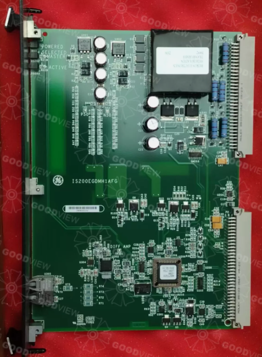
GE IS200EGDMH1AFG Exciter Ground Detector Module

Description
| Manufacture | GE |
| Model | IS200EGDMH1AFG |
| Ordering information | IS200EGDMH1AFG |
| Catalog | Mark VI |
| Description | GE IS200EGDMH1AFG Exciter Ground Detector Module |
| Origin | United States (US) |
| HS Code | 85389091 |
| Dimension | 3.2cm*10.7cm*13cm |
| Weight | 0.3kg |
Details
SPECIFICATIONS:
Part Number: IS200EGDMH1AFG
Manufacturer: General Electric
Series: EX2100
Product Type: Exciter Ground Detector Module
Number of channels: 12
Input span: 4-20 mA
Technology: Surface Mount
Common Mode Voltage Range: ±5 V
Maximum Lead Resistance: 15Ω
Analog output current: 0-20 mA
Operating temperature: -30 to 65 °C
FUNCTIONAL DESCRIPTION:
IS200EGDMH1AFG is an Exciter Ground Detector Module manufactured and designed by General Electric as part of the EX2100 Series used in GE Excitation Control Systems. The IS200EGDMH1 Ground Detection Module is used in the EX2100 Excitation Control. It is a double slot, double height (6U) form factor board that mounts in the Exciter Power Backplane rack (EPBP). The field ground detector detects field leak-age resistance between any point in the generator field circuit to the ground, either on the ac or dc side. A simplex system will have one EGDM, and a redundant system will have three. The location of the EGDM(s) is shown in Figure 1. EXAM, the attenuator module, senses the voltage across the ground sense resistor and sends the signal to the EGDM(s) over a nine-conductor cable. The EXAM module is mounted in the High Voltage Module located in the Auxiliary Panel.
In a redundant control, the set of three EGDM boards is configured as Controller (C), Master 1 (M1), and Master 2 (M2). The configuration for each EGDM is controlled by a set of program pins on the P2 connector. Information on which master provides the drive signal to the sense resistor in the Attenuator Module is sent from the DSPX, through the EISB in the controller rack, to EGDM C. Upon receiving this information over the fiber-optic link, C either powers the relay in the Attenuator Module if M2 is the driver, or leaves it unpowered if M1 is the chosen master. At the same time, a differential signal is sent to M1 and M2 that indicates the chosen master. This signal enables the signal generator on the active master and selects the test command source on each module (M1, M2, and C). Now the active master receives an Oscillator Signal over the fiber optic link from the DSPX through the EISB that it converts to a positive or negative 50-volt signal. This square wave voltage is sent by cable to the EXAM module and applied to one end of the Sense Resistor.
The signal conditioner receives an attenuated (10:1) differential signal from the Sense Resistor in the EXAM module. The signal conditioner is a simple unity gain differential amplifier with a high common-mode rejection ratio followed by an A-to-D converter (Voltage Controlled Oscillator VCO). The VCO feeds a fiber optic transmitter. The signal conditioner circuitry is powered by an isolated power supply to maintain personnel and equipment safety due to the high common-mode voltage at the Sense Resistor. The signal conditioner can measure the power amplifier output level by grounding the bridge side of the attenuated Sense Resistor on command from the control section.
FEATURES:
- The C section of the controller receives all the programming and control signals from the various sources to determine which module will be the master. It also receives the oscillator signal from the DSPX so that it can generate a test command at each transition of the oscillator signal.
- The test command is a 250 ms long signal that can be retriggered on every transition of the oscillator signal (even if the period of the signal is less than 250 ms).
- This test command is then sent to the control section of each module (M1, M2, and C) to generate a 250 ms long test signal at each positive transition of the test command. This signal is not retriggerable and therefore the transitions must be separated by more than 250 ms before another test signal can be generated.
- The power supply section receives 24 V dc from the appropriate EPSM through the EPBP (backplane). Using a dc to dc converter, it converts this into ±65 V dc (non-isolated) for the power amplifier in the signal generator section, and +5 V dc (isolated) and ±15 V dc (isolated) for the signal conditioning.
- The power amplifier output is a voltage source with an output impedance of less than 1.0 Ohm. The output voltage is a ±50 Volt squarewave with a current limited to about 80 mA, and with a normal operating period of 5 seconds. During test operation, the period reduces to 400 ms.